Description
The Incuabtion Box encloses the main body of the microscope and includes a wide array of access hatches for both sample manipulation and microscope alignment. This not only fulfils the requirement for keeping the sample at an optimal and consistent temperature but also provides improved envirnmental stability for the microscope body. The Incubator is made from black acrylic and can be produced by in-house workshops if properly equipped but is also readily outsourced using the CAD designs. The inclusion of these designs also allows this box to be adapted for use on other systems.
The Box has been designed with large hatches on both side panels for maximum acessability. These are held shut both by magnets and hinge tension to ensure that they do not open accidentally. A port is also positioned for the camera so that it is not unneccesarily heated by being enclosed and channel splitters can be added.
On the back panel, as well as an excitation beam port are 4 ports for heater hoses. Our iteration of LifeHack uses a Cube2 heater from Life Imaging Services.

Parts
All parts are made from 10mm Black 9961 Perspex except the window which is made from 10 mm clear Perspex.
Construction
👁 View CAD Design Online 👁
- After checking that you are in possession of the full set of parts tap every M4 sized hole (An electric screwdriver is a big time saver for this).
- Before connecting the main panels together, first attach each subsidiary panel to its respective main face.
- Following this, now attach the 5 main panels together to confirm the parts fit correctly.
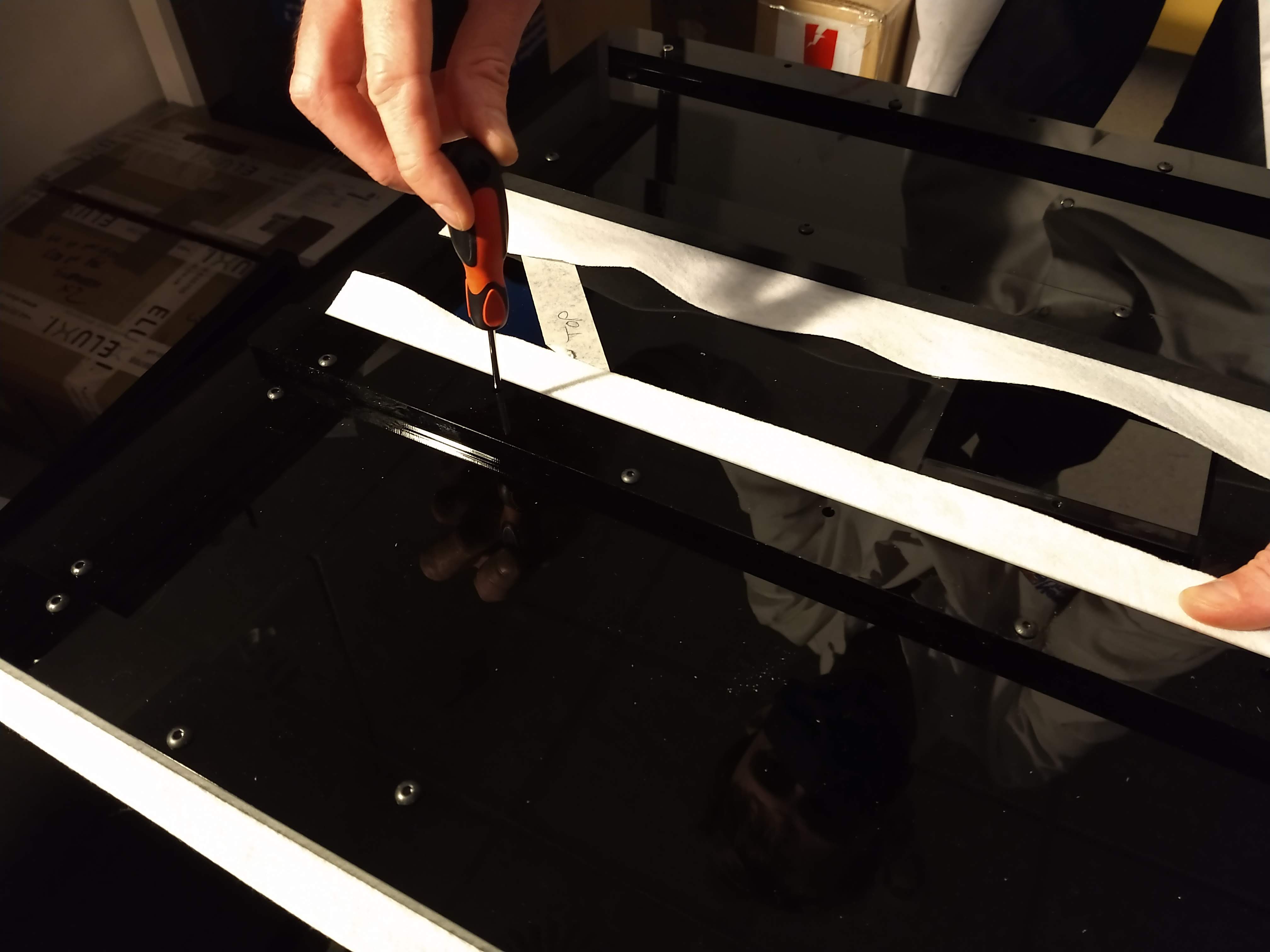
- Remove the top panel and attach the felt air diffusers as shown below.
Air Diffusers
- Remove the "top filter mounts" from the top panel to reveal the slits beneath.
- Measure and cut the diffuser felt to fit the slits.

- Pull the diffuser a short way through one of the slits and re attach the corresponding "top filter mount" to hold it in place.
- To do this, pull the diffuser to one side and attach the row of screws on the opposite side.

- Then, using a screwdriver or similar, poke through the holes on the other side to put holes through the diffuser material and attache the screws on this side.

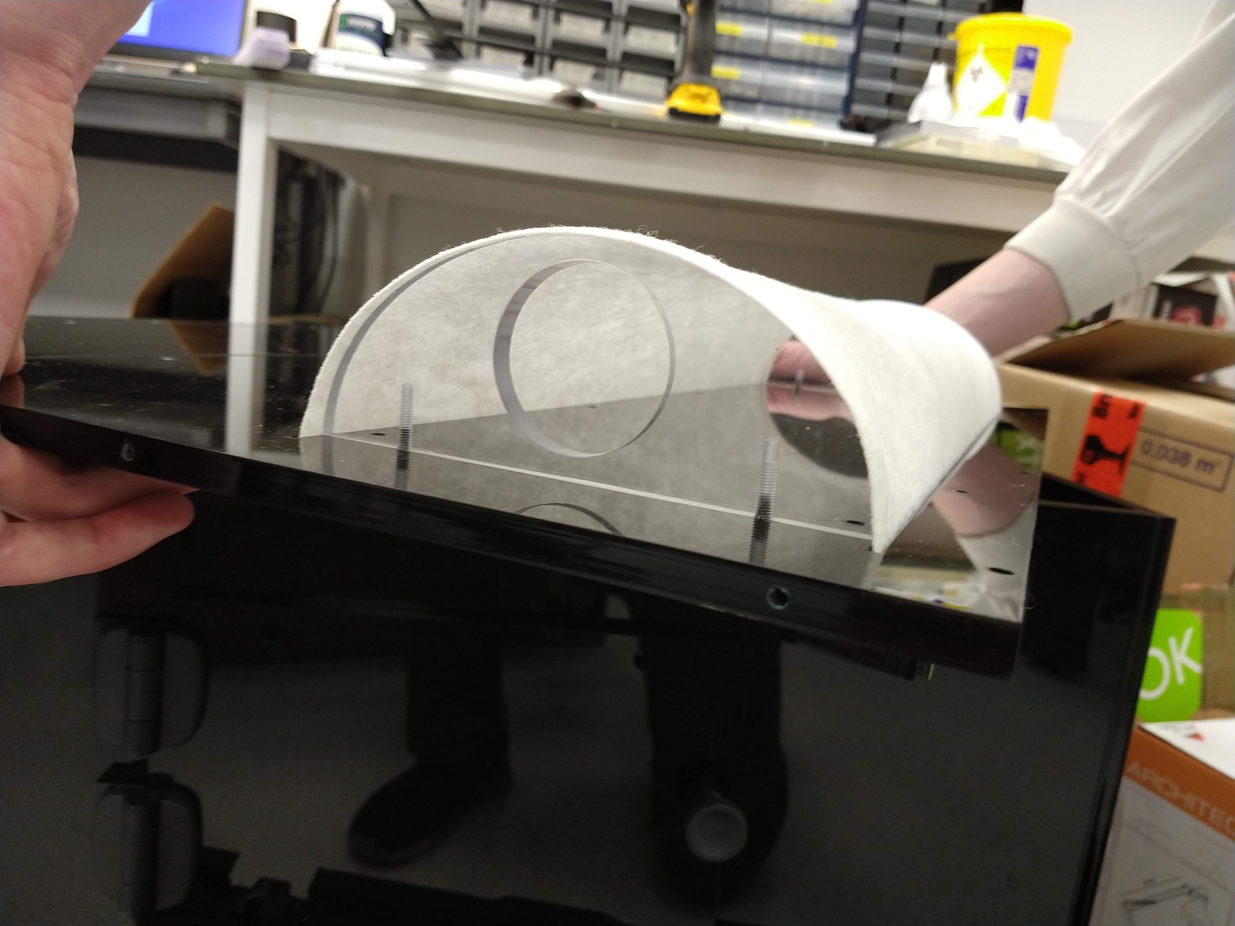
- Pull the loose side of the diffuser across the D-shaped diffuser mounts and pass it through the slit on the other side.
- Pull the diffuser taught across the mounts to ensure a good fit and secure it with the corresponding "top filter mount".

- Repeat the above steps for the second diffuser then reattach the now completed top panel to the rest of the box.
Adding the Box to the system
This is a two person job- Check the box is securely assembled before lifting.
- Open hatch doors on the two side panels and remove the "top cover" on the top panel to provide handholds.
- Remove the camera and CRISP units from the microscope "main body".
- Lift the box over the top of the "main body" and gently set it down.
Heater Setup
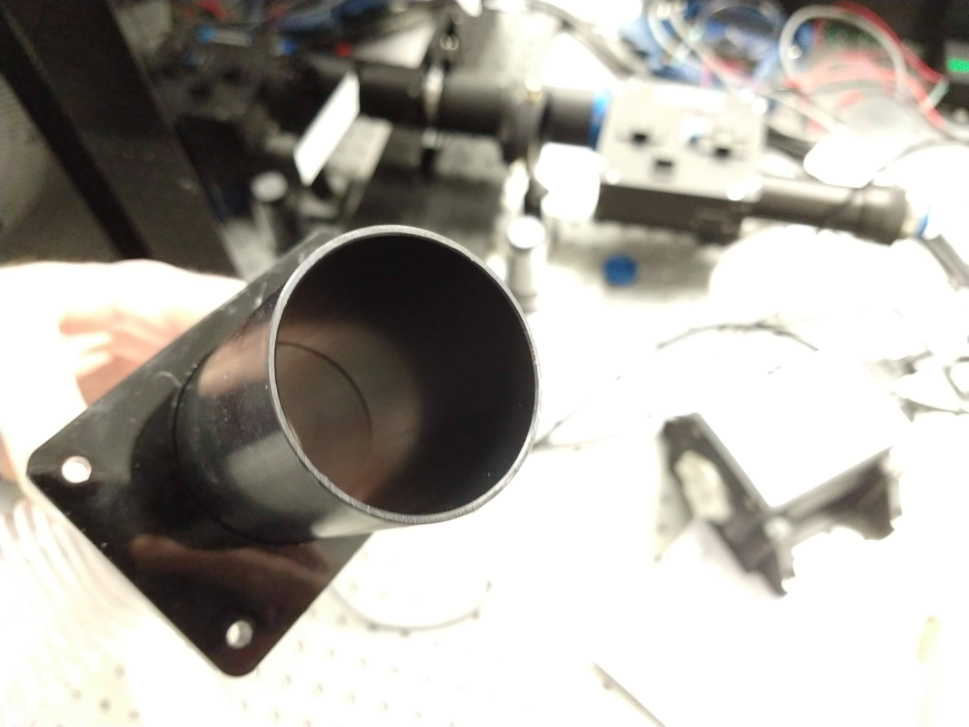
- Remove the "Back Air-hose Covers" from the box.
- Using Epoxy, for each cover attach the flared air-hose connector.

- Allow this to set for about 20 minutes (refer to epoxy for precise time).
- For the top two "Back Air-hose covers", use the Epoxy to attach the non-flared air hose connectors from the opposite side to the flared connector.

- Leave the 4 assemblies to set for 3 hours (refer to epoxy for precise time).
- Before reattaching the assemblies to the back of the box, measure and cut the air-hose to length for each of the 4 connections.
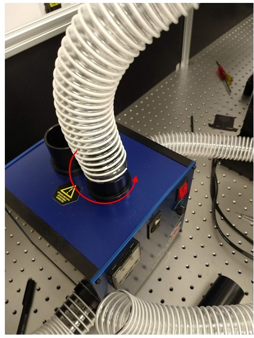
- Once cut, attach the air-hoses to the heater and then to the attachment assemblies (Utilise a screwing action following the direction of the structural wire in the air hose).

The input and output ports for the excitaition, camera, and CRISP are deliberately oversized slightly to allow for manufacturing tolerances. This means it may be neccessary to cut parts to seal these holes. We have used foam-board for large areas and neoprene for small.
